In organized industrial zones, water is managed not from a single point but through a chain that is drawn from deep wells kilometres apart, pushed stage by stage through pumping stations, and balanced in reservoirs. A level drop or a stopped motor at any link of this chain affects dozens of producing facilities by the time it is noticed hours later.
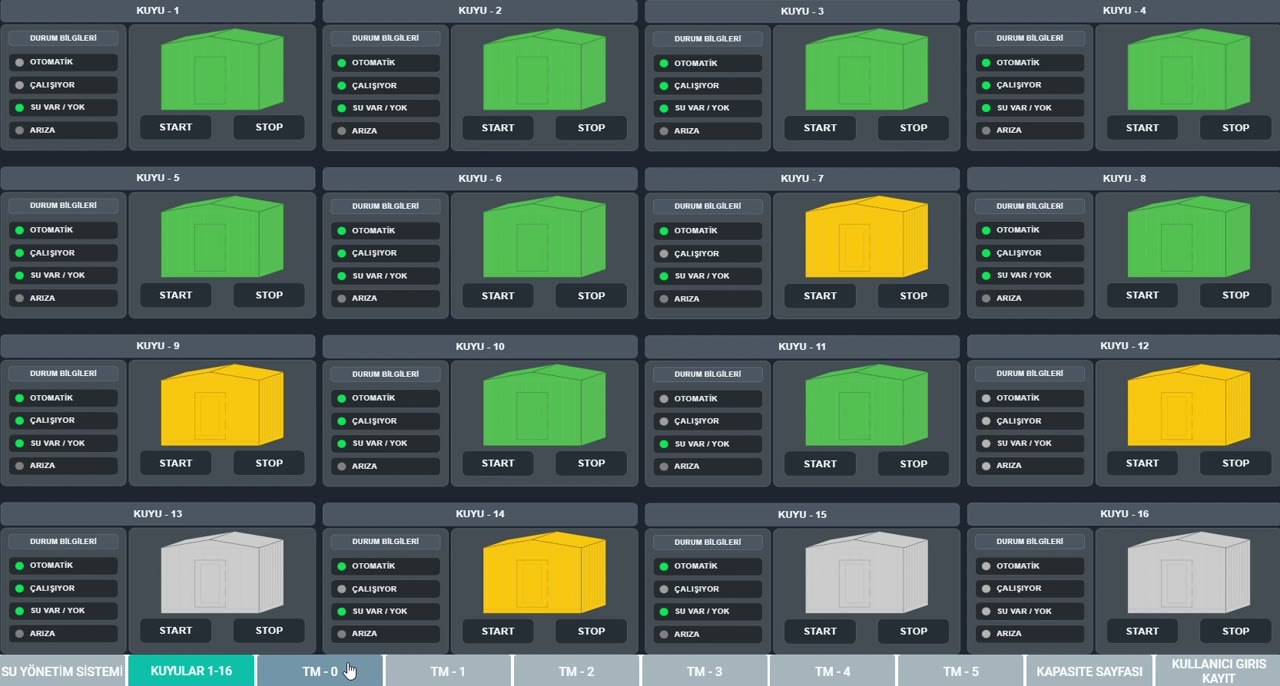
The water management system we developed for Ankara Sanayi Odası (the Ankara Chamber of Industry) as Aykome Engineering was designed precisely to solve this visibility and continuity problem. The 16 deep wells and 5 pumping stations in the field were combined into a single application on our end-to-end encrypted, cloud-based SCADA system. Operators monitor and manage the whole system on one screen through a browser.
Project scope
- 16 deep wells: Motor running status, start/stop command and auto‑manual position are monitored and controlled at each well.
- 5 pumping stations: Reservoir levels are read to centimetre precision with radar level meters; motor groups and valve statuses (open/closed/fault) are reflected on screen in real time.
- End-to-end encrypted cloud-based SCADA: All data traffic between the field and the centre is transferred encrypted; authorized users access the system over the internet with no additional software installation.
- Modbus TCP communication: All field points were connected to the central server with the Modbus TCP protocol; commissioning time was shortened by preserving the existing PLC infrastructure.
Real-time data exchange between pumping stations
The technical backbone of the project is turning the pumping stations from independent boxes into a chain that communicates in real time.
Each pumping station continuously reports its own reservoir fill ratio to the system; this information directly determines the start and stop decision of the motors at the pumping station above it. Water is pumped according to the need of the target reservoir; there is no pumping needlessly into a full reservoir or noticing an emptying reservoir too late.
Motor selection, meanwhile, is done with run-time equalization (alternating) logic. Motors at the same station are brought online in turn so their operating hours are balanced. A single motor carrying the load and wearing out early is prevented, maintenance intervals are distributed evenly across all equipment, and redundancy is preserved.
Manual and automatic operating flexibility
The system does not leave the operator outside the automation. For each well and motor, a manual or automatic operating mode can be selected instantly from the screen. While routine operation runs on automatic scenarios, control passes to the operator with a single click during maintenance, testing or unusual situations.
Multi-scenario management with four-level alarm thresholds
Four separate level thresholds — MIN, LOW, HIGH and MAX — were defined for each reservoir. These four thresholds allow different operating scenarios to be run from the same screen:
- MIN: Critical lower limit; emergency-intervention and protection scenario.
- LOW: Feed-start limit; the relevant wells and motors are brought online.
- HIGH: Feed-stop limit; needless pumping is prevented.
- MAX: Overflow-protection limit; the upper stage is stopped and an alarm is generated.
The threshold values were not hard-coded into the software. The authorized operator can change each station's limits from their own screen according to the season and operating need; no engineering support or software update is required for a scenario change.
Dual-verification operation and communication continuity
The biggest risk of a SCADA system at remote sites is that control stops entirely during an internet or communication outage. In this project, the outage was addressed as a design criterion from the start:
- Dual-verification scenario structure: Control scenarios run not only on the cloud side but on both the field PLCs and the cloud-based SCADA system. When the connection drops, the field keeps running with its own logic; when the connection returns, the two sides re-synchronize.
- High-gain antenna application: At points with weak signal, high-gain antennas were used to strengthen reception quality and minimize communication drops.
- Communication-health monitoring: Each site's connection status is monitored separately; a point whose data flow is interrupted is distinguished instantly on screen.
The result is a system that is not dependent on a single point and stays on the safe side even during an outage.
Fault notification and daily reporting
The value of a SCADA appears at the moments when no one is watching the screen:
- Instant fault email: Whatever instrument fails in the field, regardless of the hour and date, an automatic fault notification is sent to the email addresses defined by the user the moment the fault occurs.
- Daily status email: Every day at 09:00 and 17:00, a summary report containing all reservoir levels and motor statuses is sent to the email addresses of the authorized people. The sending times can be changed according to the operator's wishes.
Well information, consumption and capacity reporting
The system does not merely show the instant state; it makes the whole field measurable and reportable. The operator can track technical and operational information for each well from a single screen:
- Well depth and identity information: The depth, technical features and field information of each deep well are kept on record inside the system; the information stands on the well's own card, not in separate files.
- Daily usage report: The amount of water drawn daily and motor operating times are reported on a well and station basis.
- Monthly usage report: Periodic consumption can be taken on a monthly comparative basis; seasonal and yearly trends can be seen.
- One-touch field capacity report: The total capacity calculation of the whole field is automatically computed and reported with a single operation on screen. There is no need to calculate well by well or keep tables.
The calculation parameters were not hard-coded into the system. If desired, the values for the capacity and consumption calculations can also be set manually by the customer; the reports can be reshaped according to the operation's own assumptions and field conditions.
Thanks to these reports, water management moves from a day-saving operation to a plannable process: how hard each well is being pushed, in which period consumption rose, and where the field's real capacity limit lies are all revealed with data.
User management and access records
If a shared infrastructure is used by more than one team, who did what and when must also be part of the system. A flexible and traceable user structure was built within the project:
- Unlimited user definition: The operation can create as many user accounts as it needs; there is no upper limit on the number of users.
- 5 concurrent user access: Five users can log in and work on the system simultaneously. The field, control centre and management can see the same data at the same time.
- Access tracking via external reporting: Through a separate reporting system, who logged into the system on which date and at what time can be viewed. Actions become traceable on a per-person basis.
This structure eliminates both authorization confusion and "who made this change" disputes; it creates an auditable usage history for the operation.