Most remote monitoring projects are designed on the assumption that a ready network infrastructure exists in the field. Real fields, however, often do not match this assumption: the well is at a point outside the facility network, running a cable is costly or impossible, and all that is at hand is a panel and the PLC inside it.
In the project we carried out for Ford Otosan as Aykome Engineering, the situation was exactly that. There was no infrastructure at the site other than a single deep well and its panel; there was no Ethernet and no TCP connection. Even so, the well was made fully monitorable and reportable — independently of the rest of the facility — over our end-to-end encrypted, cloud-based SCADA system.
Field architecture and communication
- S7‑1200 PLC: The Siemens S7‑1200 PLC in the well panel was used as the hub where all measurement and control points in the field are gathered.
- Communication over GSM: Because there was no Ethernet infrastructure, data transfer between the field and the cloud was provided over a GSM line. There was no need to run a cable, interfere with the facility network or invest in additional infrastructure.
- End-to-end encrypted data transfer: All traffic between the field and the centre is carried encrypted; authorized users access the system over the internet with no additional software installation.
- Strengthening signal quality: An antenna solution suited to the site's signal conditions was applied for communication continuity; connection quality is monitored continuously from within the system.
Thanks to this architecture, the project works as a self-standing monitoring island, entirely independent of the facility network.
Well monitoring and control
Being a single-well site does not mean monitoring is simplified; on the contrary, the uninterrupted operation of that single point becomes more critical. Within the system:
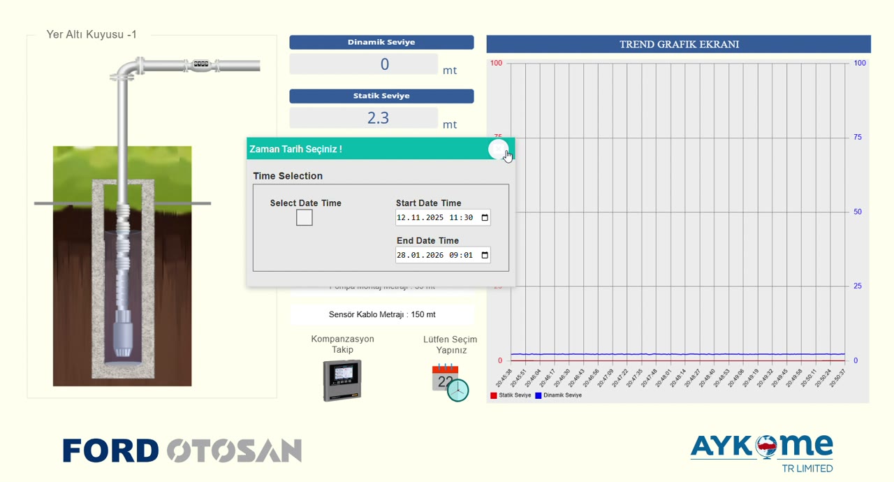
- Level tracking and four-level alarm thresholds: Four separate thresholds — MIN, LOW, HIGH and MAX — were defined over the level measurement. These thresholds manage both protection and automatic start/stop scenarios from a single screen. The threshold values were not hard-coded into the software; the authorized operator can change the limits from their own screen.
- Well identity information: The well's depth and technical information are kept on record inside the system; the information stands on the well's own card, not in a separate file.
Monitoring power-factor compensation and instant electrical values
The topic that sets the project apart from a classic well-monitoring application was the inclusion of power-factor compensation tracking in the system. A compensation panel is a system that needs to be noticed not when it fails, but when it begins to lose efficiency; and that is only possible with continuous measurement.
Items monitored through the system:
- Instant electrical values: Current, voltage and power values are reflected on screen in real time.
- Power factor (cos φ) tracking: A warning is generated when the value moves outside the target range.
- Active and reactive power monitoring: The course of reactive consumption is tracked continuously; it can be seen before a reactive-penalty risk arises.
- Compensation status: Whether the panel is engaged and whether it shows the expected behaviour are monitored.
Thus compensation ceases to be something understood from the bill at month-end and becomes a parameter managed in real time.
Dual-verification operation
On a site running over GSM, the possibility of a communication outage is a fact that must be accepted from the start. For this reason, the control scenarios were not left to the cloud side alone: the scenarios run both on the field PLC and on the cloud-based SCADA system.
When the connection drops, the well keeps running with its own logic on the PLC; when the connection returns, the two sides re-synchronize. Even if monitoring is interrupted, operation is not.
Reporting: daily, monthly and capacity
Beyond showing the instant state, the system makes the field measurable:
- Daily usage report: The amount of water drawn and motor operating times are reported on a daily basis.
- Monthly usage report: Periodic consumption can be taken on a monthly comparative basis; trends can be seen.
- Capacity report: The well capacity calculation is automatically computed and reported with a single operation on screen.
- Manually adjustable parameters: The calculation values were not hard-coded into the system; if desired, they can also be set manually by the customer.
- Electrical consumption reports: Compensation and consumption data can be tracked retrospectively.
User management and access records
- Unlimited user definition: As many user accounts as needed can be created; there is no upper limit on the number of users.
- 5 concurrent user access: Five users can log in and work on the system simultaneously.
- Access tracking via external reporting: Through a separate reporting system, who logged into the system on which date and at what time can be viewed; usage becomes auditable.
Fault notification and daily status email
- Instant fault email: Whatever instrument fails in the field, regardless of the hour and date, an automatic notification is sent to the email addresses defined by the user the moment the fault occurs.
- Daily status email: At set times, a summary report containing the well and compensation status is sent to the email addresses of the authorized people. The sending times can be changed according to the operator's wishes.